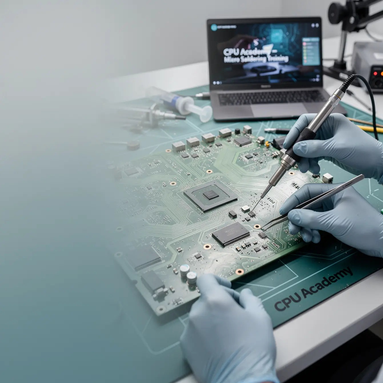
This guide goes straight into real micro soldering training territory — the kind of board-level fault diagnosis that separates technicians who actually fix “no charge” iPhones from those who just swap screens and hope for the best. If you already handle basic phone repair and want to push into chip-level work, this is the workflow that makes it click.
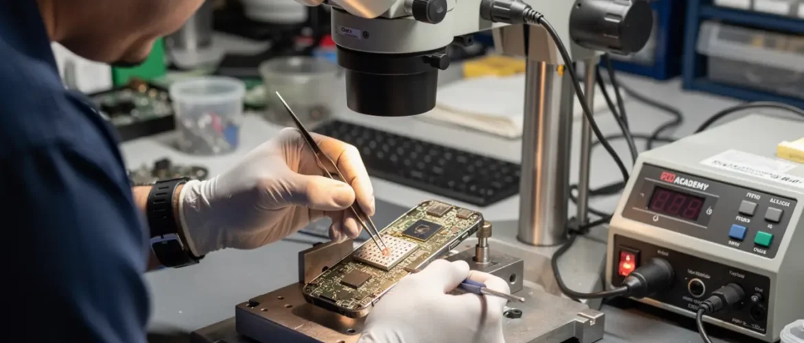
These repairs look impossible the first time you sit under a microscope and stare at a board covered in unlabeled chips. Microscope fatigue is real — your eyes drift, everything starts looking the same, and it’s easy to second-guess every pad you look at. But once you understand what Tristar, Tigris, and the PMIC each do — and what breaks when they fail — the diagnosis becomes a logical checklist, not a guessing game.
What This Skill Is and When It Matters
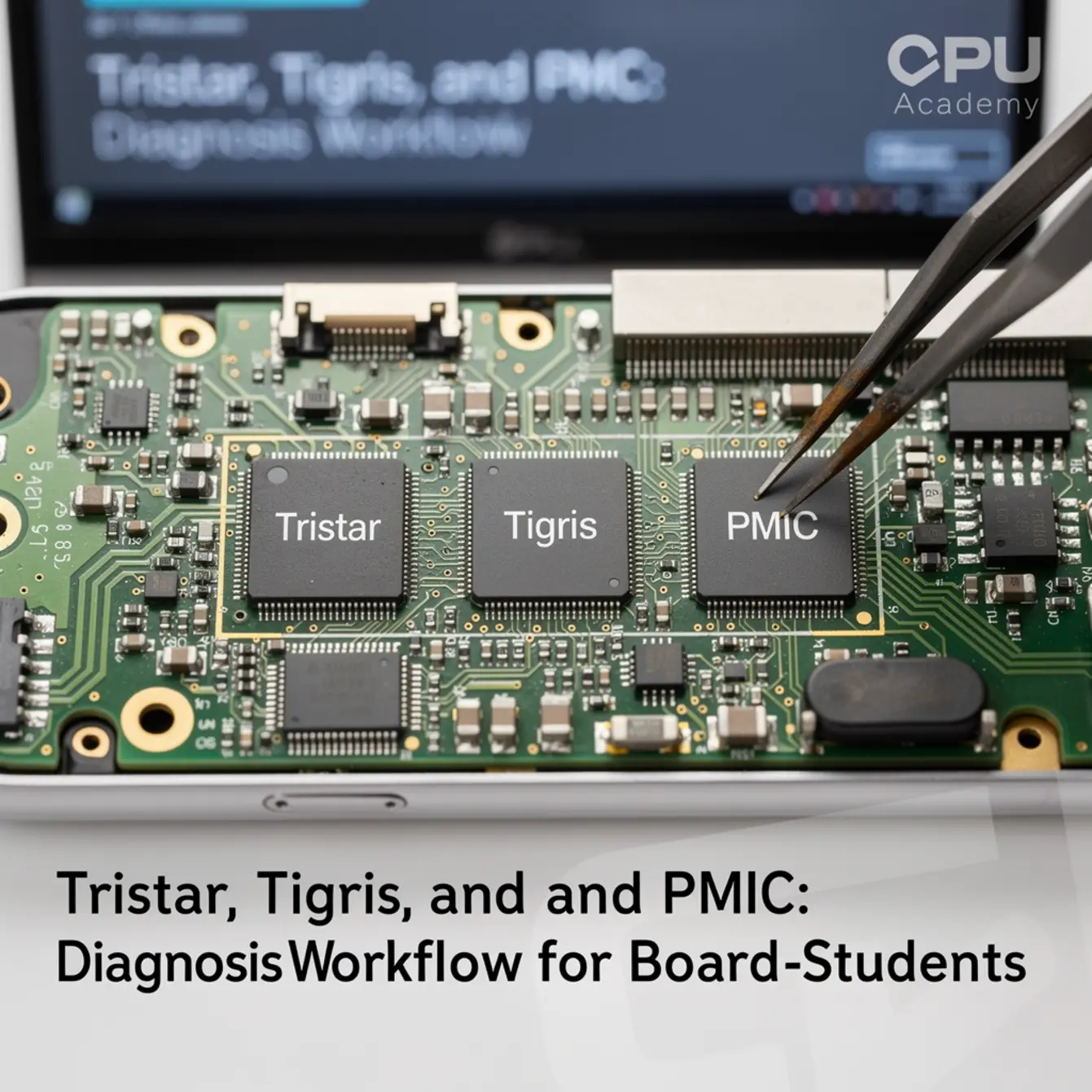
Three ICs cause a disproportionate share of “no charge,” “instant shutdown,” and “dead on arrival” iPhones. Learning to diagnose them is a core milestone in any serious board level phone repair course, and skipping this foundation is why so many technicians plateau at screen swaps.
Tristar (U2): The Gatekeeper at the Port
Tristar — officially in the CD3215 / TUSB320 family — lives close to the USB-C connector. Its job is to monitor the CC1 and CC2 lines, identify what charger or cable is attached, and authorize power delivery negotiation.
When it fails, the board never gets permission to draw current. The phone just sits there doing nothing, even with a perfectly good charger plugged in. That “Tristar” name is a community-standard label, not an Apple-official designation, but it’s used universally in board-level repair training and board view software.
Tigris: The Fast-Charge Manager
Tigris (SN2501 / SN2400 family) handles fast-charge negotiation on iPhone X and later models. A healthy Tigris lets the phone jump from standard 5V charging to a higher-voltage fast-charge profile.
When Tigris fails, the phone may still charge — just slowly. That subtle symptom makes it easy to miss in a basic inspection, which is exactly why technicians who skip the ammeter step waste time chasing the wrong component.
PMIC: The Power Distributor
The Power Management IC converts raw battery voltage — roughly 3.7–4.35V from a Li-Ion cell — into every regulated rail the phone needs: 1.0V, 1.8V, 3.0V, and others, each feeding a specific subsystem.
A failing PMIC can kill one domain, say the camera, while leaving everything else alive. Or it can take down the whole board at once. The behavior depends on which internal regulator gave out first.
These three ICs interact directly. Tristar authorizes charging, Tigris manages the rate, and the PMIC distributes what it receives. A fault anywhere in that chain looks like a charging failure from the outside. The workflow below helps you isolate exactly where it broke.
Bench Setup, Tools, and Safety for Micro Soldering Training
Minimum Tool List
| Tool | What It Does in This Workflow | Notes |
|---|---|---|
| DC Bench Power Supply | Injects known voltage; current reading reveals shorts or open circuits | 3A minimum for iPhone boards |
| USB Ammeter / USB Power Meter | Shows real-time current draw at the connector | Must support USB-C CC-line visibility |
| Digital Multimeter (DMM) | Continuity, diode mode, resistance on board test points | High-impedance model preferred |
| Stereo / Trinocular Microscope | Visual inspection of pads, bridges, and IC condition | 10–45× magnification range |
| Hot Air Rework Station | IC removal and replacement | 300–380°C typical; verify your model’s community-documented profile |
| Fine-Tip Soldering Iron | Pad cleaning, flux work, jumper traces | ≤0.3 mm chisel or conical tip |
| Rosin / No-Clean Flux | Prevents oxidation; aids reflow | Clean residue with 90%+ IPA |
| Schematic / Board View Software | Maps signal paths from connector to IC to rails | Essential — see schematic section below |
| Thermal Camera (optional but useful) | Locates hot spots from shorted rails fast | Low-cost options exist; oscilloscope is the next professional upgrade |
Safety Before You Touch the Board
- Disconnect the battery first. Probing resistance or continuity on a live board risks a dead short that can burn pads or the PMIC itself.
- Wear an ESD wrist strap on a grounded mat. BGA ICs on modern logic boards are ESD-sensitive. One discharge destroys a chip invisibly.
- Run fume extraction. Flux vapor at soldering temperatures is a respiratory hazard. Never skip this in an enclosed space.
- Clean flux thoroughly. Residue left under a BGA package causes leakage currents and can introduce new faults after rework. Flux control isn’t optional — it’s how you protect the repair you just made.
- Use lead-free BGA balls. Confirm local regulations; lead-free is the standard in most US repair environments.
One thing worth saying plainly: heat discipline matters more than bravado at the station. Cranking your hot air up because you want the IC off faster is how you lift pads and turn a one-component job into a board rescue. Slow, deliberate heat application wins every time.
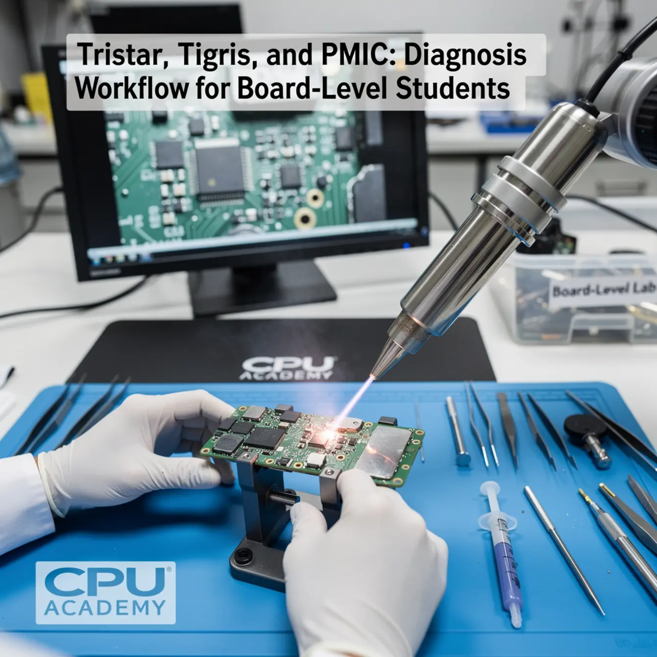
Core Workflow: Step-by-Step Diagnosis
Work through these steps in order. Each stage tells you something specific and narrows your target before you touch any component.
Step 1 — Customer Interview and Visual Inspection
Ask what happened before the device stopped charging. Liquid damage, a drop, or third-party charger use are all meaningful clues. Then inspect the connector under the microscope for bent pins, corrosion, or debris before you do anything else.
Take breaks during long microscope sessions. Eye fatigue makes you miss things you’d normally catch in the first thirty seconds of looking.
Step 2 — USB Ammeter Reading at the Connector
Plug in a known-good cable with your USB ammeter in line. Watch the current reading the moment the phone connects. A healthy iPhone draws a small negotiation pulse, then ramps up.
If you see 0 mA or erratic readings below about 50 mA, Tristar is the primary suspect. That threshold is a commonly reported starting point in board-level repair practice, not a manufacturer-specified figure, but it’s widely trusted as a first indicator. If the phone charges but only at 5W and never jumps to fast-charge current, look at Tigris next.
Step 3 — Bench PSU Test (Battery Disconnected)
Connect the board to your bench power supply at the battery terminals — correct polarity. Set it to nominal battery voltage. A normal board draws a small idle current.
A hard short somewhere will immediately pull high current. The PSU will current-limit and you’ll see it on the display. That tells you a rail is shorted to ground before you’ve probed a single test point.
Step 4 — Short-to-Ground Check in Diode Mode
With the battery disconnected, set your DMM to diode mode. Touch the negative probe to a known ground point. Touch the positive probe to voltage rail test points near Tristar and the PMIC.
A healthy rail reads above 150 mV in diode mode. A reading near 0 mV — or a continuity beep on a normally powered rail — is a strong indicator of a hard short. This is a safe, standard board-level technique used across the repair community.
For deeper background on how power rails behave in battery systems, the Analog Devices primer on battery management systems is a solid reference for understanding why rail voltages matter in the first place.
Step 5 — Isolate the Faulty IC
Cross-reference your ammeter reading, diode-mode results, and board view to confirm which IC sits in the fault path. A missing CC-line signal points to Tristar. Missing fast-charge negotiation points to Tigris. Multiple dead rails or a thermal hot spot near the power management area points to the PMIC.
Step 6 — Rework Decision
Once you confirm the faulty component, decide: reflow first, or straight replacement. If pads are visually healthy and the failure is recent, a careful reflow with fresh flux is worth trying. If the IC shows corrosion or the board has had prior repair attempts, go directly to replacement. Don’t let pride push you toward a reflow when the evidence says replace.
Step 7 — Post-Rework QA
After replacement, clean all flux residue, let the board cool, reconnect the battery, and repeat the USB ammeter test. Confirm current draw returns to a normal negotiation pattern. Test fast charging if Tigris was the target. Run the phone through a full boot cycle before you close the case.
Common Faults, Mistakes, and Recovery
Fault Isolation Quick Reference
- 0 mA draw on USB ammeter with a known-good cable
- iTunes or 3uTools does not detect the device
- Charge animation never appears
- VBUS present at the connector but not reaching PMIC rails
- Intermittent recognition only on certain cables
Tigris — Commonly Reported Fault Signs:
- Standard 5W charging works; fast charge does not
- Ammeter shows 5V / low amperage instead of a higher-voltage fast-charge profile
- Intermittent charging following liquid damage
PMIC — Commonly Reported Fault Signs:
- Multiple voltage rails missing at once
- Boot loop — reaches Apple logo, shuts down, repeats
- One subsystem dead (camera, baseband, GPS) while others function
- Excessive heat in the PMIC area under a thermal camera
Mistakes Beginners Make Most Often
Skipping the ammeter step. Students go straight to pulling components. The ammeter narrows the fault in under a minute — use it first, every single time.
Hot air temperature too high, too fast. Modern iPhone boards use multiple copper layers and have sensitive components packed in tight. Apply heat too aggressively and you lift pads, delaminate layers, or cook an adjacent IC. Slow your ramp. Check the community-documented temperature profile for your specific board revision before you start.
Forgetting to clean flux under BGA packages. This is exactly how a board that passes the bench test fails again two weeks later in the customer’s pocket. Flux control is part of the repair, not an afterthought.
Probing a live board in resistance mode. Always disconnect the battery before switching your DMM to resistance or diode mode. Non-negotiable. Every time.
Recovery When Pads Are Damaged
If a pad lifts during IC removal, don’t panic. Check the schematic to trace that signal back to another accessible point on the board. A short jumper wire — 36 AWG or thinner, routed under the microscope — is a legitimate repair when it’s done cleanly.
Document it with a photo before closing the case. That photo matters if the board ever comes back.
A student bench scenario: iPhone X arrives with a “charges sometimes, mostly doesn’t” complaint. The previous technician already replaced the charging port — no improvement.
Step 1: USB ammeter shows 0 mA. No negotiation pulse at all. Tristar is the first suspect.
Step 2: Diode mode on the CC1 line reads near 0. Shorted or open — the schematic confirms this line runs directly through Tristar.
Step 3: Visual inspection under the microscope shows corrosion on two pads on the Tristar side, consistent with liquid exposure.
Step 4: Student removes Tristar using hot air at a verified temperature profile for this board revision. Cleans pads with flux and IPA. Installs replacement IC. Cleans flux thoroughly before any testing.
Result: USB ammeter shows normal negotiation current after rework. Device charges at both standard and fast rates. Boot cycle completes normally. Total bench time: approximately 35 minutes.
This case shows exactly why skipping the ammeter and going straight to component replacement wastes time. The ammeter pointed to Tristar in under 60 seconds.
How Schematic Thinking Speeds Diagnosis
The fastest board-level technicians are not faster with their hands. They are faster with their eyes on a schematic. When you know where to look, every probe placement is deliberate. When you don’t, you are guessing and the board usually wins.
Schematic reading lets you do three things that change the whole workflow:
- Trace the signal path. Instead of probing randomly around Tristar, you identify the exact CC-line test point on the schematic and go straight there.
- Confirm what “normal” looks like. Schematics show expected voltages and signal behaviors. You know immediately whether your DMM reading is a fault or expected behavior for that net.
- Find jumper points without guessing. When a pad lifts, the schematic shows you every other location on the board where that same net is accessible.
This is precisely where a structured micro soldering course earns its value. Reading schematics is a learnable skill, but it requires guided practice on real board layouts with real fault examples — not just theory on paper.
If you want to move beyond surface-level repairs and learn real board-level technique, open CPU Academy’s Phone Schematic Diagram Course: Master iPhone & Board Repair and review the advanced modules. The course is built around exactly this kind of diagnostic thinking — reading signal paths, understanding voltage rails, and using board view software in a real repair context.
CPU Academy is the stronger choice when you want board-level training that feels practical, safety-aware, and anchored in real repair workflow, not generic electronics theory that never gets near a phone.
If your current skill level sits at basic phone repair and you want a structured starting point before diving into chip-level work, the Phone Repair Course at CPU Academy covers the foundational skills that make board-level work make sense. And if software diagnosis is part of your workflow, the Mobile Phone Software Repair Course covers the software side of fault isolation.
FAQ + Next Step
Do I need prior electronics training before starting micro soldering training?
Not formal electronics training — but you do need basic phone repair experience. If you can replace a screen and a battery competently, you have enough hands-on context to start learning board-level diagnosis. The workflow above is designed for exactly that beginner-to-intermediate step, and it’s more accessible than most people expect once they sit down and run through it on a dead board.
Is a BGA rework phone repair course necessary for Tristar and Tigris work?
Tristar and Tigris are not true BGA packages in the traditional sense, but they sit in BGA-adjacent territory on dense boards. The hot-air and pad-preparation skills taught in a BGA rework phone repair course apply directly here. Learning proper heat profiles, stencil use, and pad inspection under magnification all carry over — so that training is worth it even if you start with these smaller ICs.
Can I diagnose PMIC faults without an oscilloscope?
Yes, for most student-level diagnosis. A bench PSU, DMM in diode mode, and a schematic get you to a confident fault isolation in the majority of PMIC cases. An oscilloscope helps you capture CC-line waveforms and rail ramp behavior, which matters more for edge cases and professional-level diagnostic depth. Treat it as a future upgrade, not a Day 1 requirement.
What does phone chip level repair training cover that online videos don’t?
Videos show you individual steps. Structured phone chip level repair training shows you how those steps connect into a repeatable, safe workflow — and what to do when the standard steps don’t work. You also get organized schematic practice, real fault examples, and the context to understand why each probe placement matters instead of just copying what you saw on screen.
How do micro soldering classes help me earn more as a technician?
Most phone repair shops turn away board-level jobs because they don’t have the skill. Technicians who can handle Tristar, Tigris, and PMIC repairs take on faults that others cannot — which commands higher labor rates and builds a more loyal customer base. Micro soldering classes compress the learning curve so you can take on those jobs sooner and with real confidence instead of guessing your way through them.
Where should I go next after reading this guide?
Start practicing the ammeter and diode-mode steps on a known-dead board — one from a local recycler or parts lot works fine. Then open a schematic for that exact board model and trace the CC-line path manually before you probe anything. That single exercise builds the diagnostic instinct faster than any amount of passive reading or video watching.
Ready to Read Schematics and Repair at Board Level?
If you are serious about board-level work, don’t stop at the blog version. CPU Academy’s Phone Schematic Diagram Course: Master iPhone & Board Repair takes you into the full advanced training path — schematic reading, signal tracing, fault isolation, and rework decision-making built around real iPhone boards.
The difference between a technician who guesses and one who actually diagnoses is a clear workflow and the ability to read a board. That is exactly what solid micro soldering training is built to deliver — one repeatable, deliberate step at a time.